

What Does an Ozone Aging Chamber Test? Standards and Operating Methods

1. Working Principle and Structural Composition of Ozone Aging Chamber
1. Working Principle
Trace atmospheric ozone attacks unsaturated double bonds in the molecular chains of rubber and thermoplastic rubber, causing molecular chain scission and surface cracking perpendicular to tensile stress. The failure process that takes several years under natural aging can be accelerated to 24–168 hours inside the chamber. The Ozone Aging Chamber generates ozone via silent corona discharge: dry and clean compressed air passes through high-voltage discharge tubes, where O₂ is ionized into O atoms and recombined into O₃. A built-in PID closed-loop control system collects real-time feedback from the ozone sensor and automatically adjusts the generator power to stabilize ozone concentration. Circulating fans force convection to ensure uniform ozone distribution inside the chamber. Full light shielding of the chamber eliminates ultraviolet interference, complying with the light-free test requirements of GB/T7762.
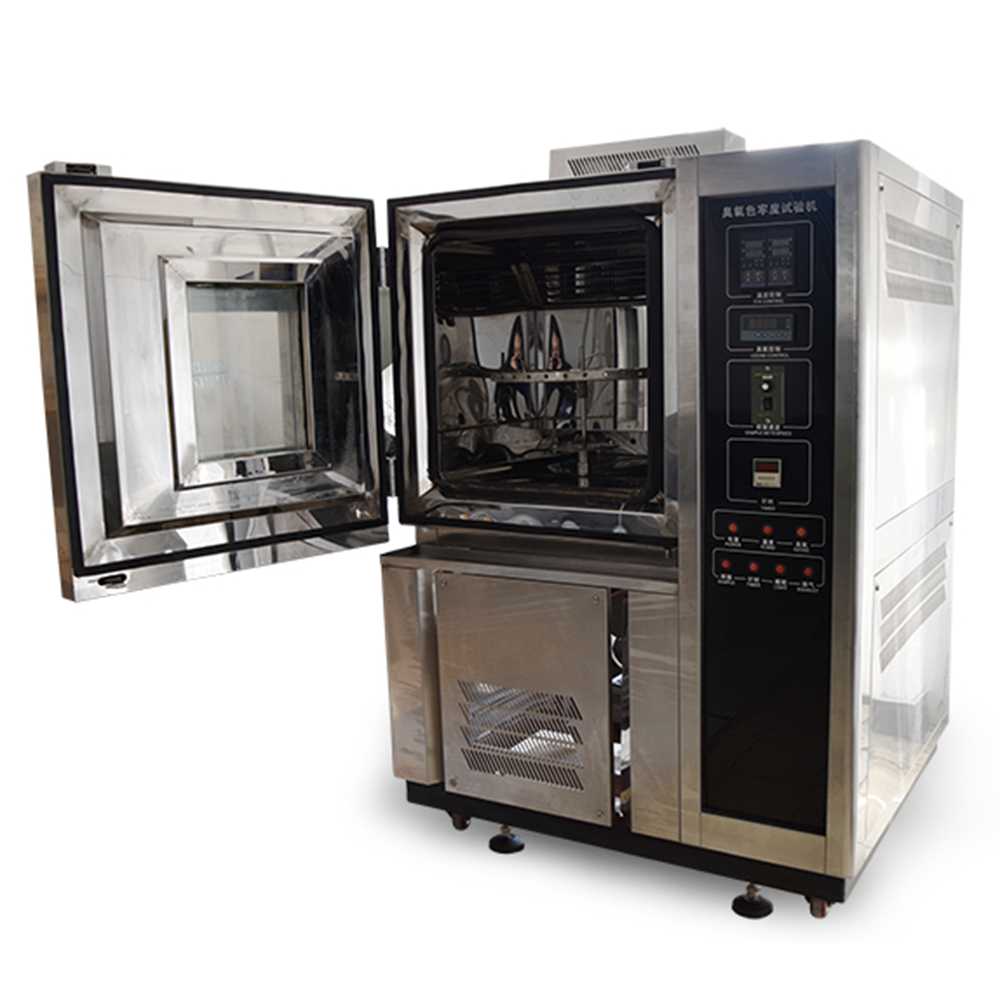
2. Overall Structure (Measured Standard 150L Model)
Ozone Generation System: Tubular ozone generator, drying and filtering assembly, pressure regulating solenoid valve; inlet air dew point ≤ -40℃ to avoid ozone yield loss caused by water vapor.
Temperature & Humidity Control System: Heating tubes, refrigeration compressor, humidifier, platinum resistance temperature sensor.
Concentration Measurement & Control System: Electrochemical ozone sensor, PLC controller, 4–20mA signal transmission, measured in accordance with JJF2051-2023.
Specimen Loading System: Static tensile frame (adjustable strain: 0–40%), dynamic reciprocating tensile mechanism (standard frequency: 2r/min), 360° rotating sample rack.
Circulating Air Duct System: Centrifugal circulating fan, airflow velocity inside chamber: 12–16mm/s, concentration uniformity error ≤ ±8%.
Safety Post-treatment System: Ozone decomposition catalytic converter, interlock shutdown for over-temperature/over-concentration, waste gas exhaust pipeline, negative pressure self-locking cabin door device.
Chamber Body: Internal volume 150L, internal dimensions 500×500×600mm, corrosion-resistant SUS304 stainless steel inner wall, double-layer heat-insulating tempered observation window.
2. Technical Parameters and Performance Indicators
(Standard 100–500L models commonly used in the industry; all data complies with the metrological specifications of JJF2051-2023)
Temperature range: 0℃~70℃; constant at 40℃ for standard tests, temperature fluctuation ±0.5℃, temperature uniformity ≤±2℃.
Ozone concentration range: 10–1000pphm; conventional test gears: 25±5pphm, 50±5pphm, 100±10pphm; concentration control accuracy ±10%.
Relative humidity: 60%~95% RH, 65% RH for conventional tests, humidity control accuracy ±3% RH.
Circulating airflow rate: continuously adjustable from 20–70L/min.
Specimen strain: linearly adjustable static strain 0–40%; dynamic tensile travel 5%–45%, reciprocating frequency 2r/min.
Ozone uniformity inside chamber: concentration range difference at any five measurement points ≤10%.
Power supply: AC220V±5%/50Hz, rated power 7.5kW for 150L model.
Safety protection: Four interlock protections for over-temperature, excessive ozone concentration, fan failure and cabin door opening. After exceeding limits, catalytic decomposition empties ozone, and the ozone concentration inside the chamber drops below the safety threshold of 0.1ppm within 30 seconds.
Metrological acceptance requirements: Calibrated annually per JJF2051-2023; qualified if concentration indication error ≤±10% and temperature indication error ≤±0.8℃.
3. Installation, Commissioning and Operating Procedures
(I) Installation Specifications
Placement environment: Laboratory ambient temperature 23±2℃, ambient humidity 20%–80% RH; keep away from direct sunlight, air conditioner vents and heat sources; ground levelness error ≤2°; reserve maintenance space ≥800mm around the equipment; exhaust pipeline leads directly outdoors; direct indoor discharge of ozone waste gas is prohibited.
Air source matching: Connect clean oil-free dry air compressor with air dew point ≤-40℃ and pressure 0.4–0.6MPa; absence of a dryer will reduce ozone output by over 30%.
Electrical wiring: Independent regulated power supply (power ≥1.2 times the rated power of the equipment) with reliable grounding; grounding resistance <4Ω to prevent sensor signal drift.
Pipeline sealing: PTFE tubes used for ozone delivery; ozone-resistant sealant applied to all joints. Perform pressure holding test for 30 minutes after installation; no leakage is confirmed if pressure drop ≤0.02MPa.
(II) Commissioning Steps
No-load trial operation: Run continuously for 2 hours at 40℃ and 65% RH without ozone generation; record temperatures at five points and proceed only after uniformity meets standards.
Ozone system commissioning: Run no-load for 4 hours with concentration set to 50pphm; record concentration every 30 minutes; stable if fluctuation ≤±5pphm.
Tensile mechanism calibration: Calibrate static strain at 10%/20%/30% with calipers, error ≤±0.5%; repeatability error of dynamic reciprocating travel ≤0.3mm.
Interlock safety test: Manually open the cabin door; the ozone generator shuts down immediately and the catalytic decomposition system starts automatically.
(III) Standard Operating Procedures (Taking GB/T7762 Static Test as Example)
Specimen preconditioning: Cut specimens per standards, then condition for 24 hours at 23℃/50% RH to eliminate residual processing stress.
Specimen clamping: Fix strip specimens on the tensile frame and stretch to specified strain (conventional 20%) to avoid stress concentration at specimen edges; cut surfaces may be sealed with sealant as required by Appendix D of ISO1431-1:2024.
Close and lock the door, set parameters: Temperature 40℃, humidity 65% RH, ozone 50pphm, test duration (24/48/72/168h).
Equipment startup: Activate temperature and humidity circulation first; the ozone generator turns on automatically after internal temperature and humidity stabilize for 30 minutes.
Routine inspection during test: Stop equipment every 24 hours to evacuate ozone for 15 minutes; inspect cracking through the observation window with a 5–10× magnifying glass and record cracking time and crack grade.
Test completion: The program stops ozone generation automatically and performs catalytic decomposition for 30 minutes; open the door for sampling only after internal ozone concentration falls below 0.1ppm.
Specimen storage: Take photos to record appearance and complete tensile and hardness mechanical tests.
4. Maintenance Specifications for Ozone Aging Chamber
1. Before Daily Startup (Mandatory before each test)
Check dew point of air compressor dryer and pipeline air leakage; listen for abnormal fan operation noise; confirm the fan of catalytic decomposition unit works normally; clean stains on observation window.
2. Weekly Maintenance
Wipe dust off the ozone sensor probe; clear rubber debris at the chamber bottom; drain accumulated water in the humidifier and replace deionized water; inspect cabin door sealing strips for hardening and cracking.
3. Monthly In-depth Maintenance (Completed before mandatory metrological calibration)
Remove generator housing and dedust high-voltage electrodes.
Perform single-point calibration on temperature and ozone sensors to adjust zero voltage to standard 40mV.
Clear circulating air duct filter screen; clogged ducts cause chamber concentration deviation exceeding 15%.
Inspect bearings of tensile mechanism and add silicone-based grease.
Repeat air tightness test: Hold pressure for 30 minutes; replace PTFE pipe joint seals if pressure drop exceeds standard.
4. Quarterly Maintenance
Replace ozone catalytic decomposition filter element; calibrate frequency and travel precision of dynamic tensile mechanism; fasten all electrical terminal lugs.
5. Annual Maintenance
Entrust metrology institute to conduct full-parameter calibration per JJF2051-2023; replace aged discharge tubes of ozone generator; fully replace thermal insulation layers and sealing strips of the whole machine; perform electrical insulation test.
Maintenance Prohibition: Do not wipe sensor probes with acetone or alcohol, which causes permanent failure of electrochemical probes; only neutral deionized soft cloth is allowed for chamber cleaning.
5. Ozone Aging Test Standards and Methods
(I) Current Standards (Domestic & International, Mandatory Basis for Model Selection and Report Issuance)
Domestic National Standards
GB/T7762-2014: Vulcanized rubber and thermoplastic rubber — Resistance to ozone cracking — Static tensile test (equivalent to ISO1431-1)
GB/T13642-2015: Vulcanized rubber — Resistance to ozone cracking — Dynamic tensile test (equivalent to ISO1431-2)
GB/T2951.21-2008: Ozone resistance test for cable insulation and sheaths
GB/T11206-2009: Evaluation method for surface cracking of aged rubber
International Standards
ISO1431-1:2024: Ozone cracking under static strain
ISO1431-2: Ozone cracking under dynamic strain
ASTM D1149 (static test), ASTM D1171 (dynamic test)
HG/T7286.9: Static ozone resistance evaluation for rubber hoses
(II) Two Core Test Methods (Fixed Measured Parameters)
Static Tensile Method (GB/T7762, for general formula comparison and sealing part inspection)
Standard working conditions: 40℃, 65% RH, ozone 50±5pphm; specimen strain 10%/20%; duration 24–168h.
Applicable products: Automobile door and window sealing strips, silicone rubber, EPDM, construction sealant.
Judgment index: Qualified if no cracking occurs within 72 hours (crack grade 0–1).
Dynamic Tensile Method (GB/T13642, simulating reciprocating stress conditions)
Standard working conditions: 40℃, ozone 50pphm, tensile reciprocating frequency 2r/min, deformation range 0–25%.
Applicable products: Shock-absorbing rubber, transmission belts, brake hoses, cable sheaths; simulates vehicle bumping and mechanical reciprocating deformation to accelerate crack propagation.
(III) General Concentration Selection Rules (Directly matched by product)
25pphm: Products with low ozone resistance (benchmark test for EPDM and fluororubber)
50pphm: Factory inspection of general rubber, cables and auto parts (mainstream standard in the industry)
100pphm: Severe accelerated tests, new material formula screening, simulation of high-ozone plateau environments
6. Fault Diagnosis and Troubleshooting Solutions for Ozone Aging Chamber
Fault 1: Continuous drift of ozone concentration, fluctuation >±15pphm
Causes: Dust accumulation/zero drift of sensor, pipeline air leakage, air compressor dryer failure.
Solutions: Clean probe and calibrate zero point to 40mV per JJF2051; replace PTFE sealing joints; overhaul dryer to ensure dew point ≤-40℃.
Fault 2: Partial chamber area without ozone, uneven aging effect on specimens
Causes: Clogged circulating air duct filter, insufficient fan speed.
Solutions: Shut down, cool down and evacuate ozone; disassemble air duct to clear rubber debris; inspect fan capacitor and replace damaged fan.
Fault 3: No ozone output after startup, concentration remains 0pphm
Causes: Dust-covered high-voltage electrodes, insufficient air source pressure, triggered interlock protection.
Solutions: Dedust electrodes; adjust air compressor pressure to 0.4–0.6MPa; reset cabin door safety lock and over-temperature protection switch.
Fault 4: Unstable temperature with continuous deviation over ±3℃
Causes: Offset platinum resistance temperature sensor, dust-clogged condenser, damaged heating contactor.
Solutions: Calibrate temperature probe; blow cooling condenser with high-pressure air; replace SSR solid-state relay.
Fault 5: Safety alarm triggered even with closed cabin door, equipment fails to start
Causes: Poor contact of cabin door limit switch, stopped exhaust catalytic fan.
Solutions: Adjust position of door control switch; replace catalytic cooling fan.
Fault 6: Dynamic tensile mechanism fails reciprocating motion
Causes: Overloaded reduction motor, offset limit sensor.
Solutions: Clear debris on tensile track; calibrate travel photoelectric limit and run no-load test.
7. Safe Operation and Protection Requirements
(The human hazard threshold of ozone is 0.1ppm; all rules must be strictly implemented)
Personal Protection Operation Requirements
Perform 30-minute ozone catalytic evacuation before opening the door for sampling; open the door only after internal concentration drops below 0.1ppm.
Wear KN95 dust and gas masks and ozone-resistant nitrile gloves during routine inspection; direct skin contact with high-concentration ozone gas is prohibited.
Install online ozone alarm in laboratory compulsorily with alarm threshold set to 0.05ppm; shut down equipment and ventilate immediately upon alarm.
Red Lines for Equipment Safety (Illegal operation prohibited)
Do not run equipment without connected exhaust pipeline or activated catalytic decomposition unit; avoid direct sunlight on the chamber to prevent photochemical reactions.
Do not place oil or volatile organic solvents inside the test chamber; such substances consume ozone and corrode stainless steel inner walls.
Forcibly opening the cabin door during equipment operation is forbidden; instantaneous leakage of high-pressure ozone irritates respiratory tracts and damages corneas.
Cut off power supply of ozone generator immediately when equipment fault alarm activates; live disassembly of generator modules is prohibited.
Equipment Fire Safety Requirements
Flammable rubber and solvents are forbidden to be stacked within 1m around equipment; the whole machine is equipped with independent leakage protection switch with leakage action current ≤30mA.
Test activity of catalytic decomposition filter element annually; failed filter elements cause excessive ozone discharge of waste gas.
8. Ozone Concentration Control and Calibration Methods
(Fully complies with metrological specification JJF2051-2023, essential for laboratory metrology)
1. Daily Closed-loop Control Principle
Electrochemical sensor collects real-time ozone concentration inside the chamber and transmits signals to PLC. The PID algorithm calculates the difference between set value and measured value to automatically adjust high-voltage output power of ozone generator: reduce discharge power for excessive concentration and increase power for insufficient concentration to realize real-time stable regulation.
2. Periodic Calibration Specifications (Mandatory execution)
Monthly internal simple calibration: Single-point comparison using standard ozone calibration gas (50pphm standard source); re-zeroing required if indication error >±10%.
Annual legal metrological calibration: Entrust third-party metrology institute to perform five-point concentration calibration (25/50/100/200/500pphm), simultaneously verify temperature and airflow uniformity, and issue metrological calibration certificate valid for 12 months.
3. Calibration Operating Steps (Practical Operation Flow)
Run equipment no-load for 2 hours until temperature and humidity stabilize at 40℃/65% RH.
Connect standard calibration gas source to chamber sampling port and seal the chamber tightly.
Feed standard ozone gas of each concentration level sequentially and record displayed concentration after 30-minute stabilization.
Calculate indication error; adjust sensor ZERO potentiometer to standard zero voltage of 40mV if zero offset exceeds 5mV.
Save calibration records after calibration and archive for 3 years.
Key Control Data: Sensors must be replaced after 18 consecutive months of use; aged probes produce persistent negative concentration deviation exceeding 20%.
9. Specimen Preparation and Test Result Analysis
1. Standard Specimen Preparation Requirements (Unified cutting and sample making standard)
Strip specimens for static test: Width 10mm, thickness 2.0±0.2mm, length 150mm; surface free of scratches, bubbles and impurities; seal cut edges with sealant to eliminate stress concentration.
Dumbbell specimens (for re-test of tensile properties): Comply with GB/T528, total length 115mm, parallel section width 6mm.
Specimen preconditioning: Condition cut specimens at constant temperature and humidity of 23℃/50% RH for 24 hours; unconditioned specimens crack prematurely and produce invalid test data.
At least 3 parallel specimens for each test group, with blank control specimens placed simultaneously.
2. Result Observation and Quantitative Analysis (Crack Grading Standard GB/T11206)
Visual crack grading (Grade 0–5)
Grade 0: No cracks (optimal); Grade 1: Fine hairline cracks, length <0.5mm; Grade 2: Short thin cracks, 0.5–2mm; Grade 3: Medium cracks, 2–5mm; Grade 4: Long cracks, 5–10mm; Grade 5: Penetrating large cracks, material fracture (failure).
Mechanical property judgment (Tested after 72h aging)
General acceptance standard for auto sealing parts: Tensile strength retention ≥80%, elongation at break retention ≥75%, Shore A hardness change ≤±5HA.
Data judgment rule: If 2 or more out of 3 parallel specimens reach failure grade, the material is judged unqualified for ozone resistance. Cracks perpendicular to tensile stress are typical ozone cracks; parallel cracks are processing defects and not counted as aging failure.
10. Application Fields and Model Selection Guide
(I) Core Test Objects (What the ozone aging chamber tests)
Targeting polymer materials containing unsaturated double bonds, the equipment simulates accelerated atmospheric ozone aging to test cracking, elasticity attenuation and sealing failure.
Rubber products: NR natural rubber, SBR styrene-butadiene rubber, BR polybutadiene rubber, CR neoprene, EPDM sealing strips, hoses, shock-absorbing pads, wiper strips, tires.
Cable materials: Rubber insulation and sheath of wires and cables, rail transit cables, mining cables.
Rubber and plastic accessories: Sealing parts for automobile doors/windows/skylights/engines, fuel hoses, brake hoses.
Construction materials: Curtain wall sealant, door and window rubber strips, waterproof coiled materials, expansion joint fillers.
New material research and development: Comparative screening of ozone-resistant additives, fluororubber and silicone rubber formulas.
(II) Model Selection Parameters by Scenario (Direct reference for procurement)
Laboratory formula research (small batch specimens): 100L chamber, concentration range 10–500pphm, static tensile only; suitable for material comparison, low price and small footprint.
Quality inspection of auto parts/cable factories (mass production sampling): Standard 150L model, static + dual dynamic tensile mechanism, concentration range 10–1000pphm, support unattended 72-hour operation; standard mainstream model in the industry.
Third-party testing laboratories (CNAS certified): Large 500L chamber, 360° rotating sample rack, five-point uniform concentration calibration, interface supporting metrological certificates, meeting ISO/GB test report requirements.
Severe accelerated test selection: Optional high-temperature extended model (max. 80℃) and high-concentration 1000pphm model for simulation of plateau and heavy industrial pollution environments.
(III) Key Points to Avoid Pitfalls in Model Selection (Key inspection items for procurement)
Reject simple models without electrochemical sensors; ultraviolet ozone probes have concentration error exceeding 25% and cannot issue compliant test reports.
The chamber must be fully made of 304 stainless steel; galvanized chambers corrode and leak ozone within 3 months.
Catalytic decomposition waste gas system must be equipped; models without tail gas treatment fail laboratory safety specifications.
For dynamic test requirements, confirm stable tensile frequency of 2r/min and travel repeatability error ≤0.3mm.
11.Viewpoints
The core error sources of ozone aging tests are not equipment hardware, but three types of human management omissions: insufficient specimen preconditioning, chamber air leakage and overdue sensor calibration. 80% of data distortion arises from failure to strictly implement JJF2051 calibration and 24-hour temperature-humidity specimen conditioning.
Static test at 50pphm, 40℃ for 72 hours serves as a universal accelerated benchmark for automobile rubber parts, yet it cannot be directly converted to natural service life and is only used for horizontal comparison of identical formulas. Combined aging verification including ultraviolet, damp heat and temperature cycling must be added if predicting actual outdoor service life.
Saturated rubbers (EPDM, fluororubber, silicone rubber) contain no molecular double bonds and possess far superior ozone resistance to natural rubber. Mass cracking during tests shall be attributed to formula fillers and residual processing stress first instead of simply judging the material as ozone-unresistant.
In equipment operation and maintenance, ozone generators and electrochemical sensors are consumables. Stocking spare parts in advance based on the 18–24 month replacement cycle can greatly reduce production line and laboratory testing downtime. Equipment without tail gas catalytic decomposition devices brings hidden risks of ozone poisoning in laboratories and fails audit requirements of CNAS and factory EHS management systems.
2026-07-08 11:01
- Related News
How to Choose a Suitable Drying Rate Tester?
What Is a Fabric ICI Pilling and Snagging Box?
How to Choose an ICI Mace Snag Tester?
What a Fiber Oil Extractor Actually Does?
Snap Button Pull Tester: Garment Accessory Tensile Strength Testing Guide
Guide to Block-on-Ring Friction Wear Equipment
How to Choose Universal Multifunction Tribology Test Machine
How to Choose an Air-Cooled Xenon Lamp Aging Chamber
What Does an Ozone Aging Chamber Test? Standards and Operating Methods
Fabric Cool Feeling Tester: Working Principle, Standards and Selection Guide