OSU Rate of Heat Release Apparatus ASTM E906
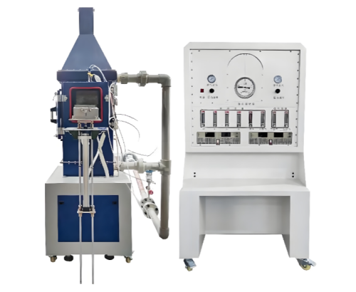


1. Scope of Application
Applicable to the heat release rate test of non-metallic materials used in the interior of civil aircraft cabins.
2. Compliance with Standards
2.1 Complies with the requirements of FAR 25 Appendix F, Part IV — "Test Method to Determine Heat Release Rate of Cabin Materials Under Thermal Radiation" of the U.S. Federal Aviation Regulations (FAR).
2.2 Complies with the requirements of ASTM E906/E906M-21 — "Standard Test Method for Heat and Visible Smoke Release Rates for Materials and Products Using a Thermopile Method."
2.3 Complies with the requirements of CCAR-25-R4 (China Civil Aviation Regulations, Transport Category Airplanes Airworthiness Standards), Appendix F, Part IV — "Test Method to Determine Heat Release Rate of Cabin Materials Under Thermal Radiation."
2.4 Complies with the requirements of HB 7399-2022 — "Test Method for Heat Release Rate of Non-Metallic Materials Used in Civil Aircraft Cabin Interiors."
3. Main Technical Parameters
3.1 Heat Release Rate Measurement Apparatus
3.1.1 All external surfaces of the equipment, except for the operation cabinet, are insulated with 25 mm thick low-density high-temperature-resistant fiberglass insulation material.
3.1.2 The specimen insertion rod adopts a sliding mechanism and passes through an airtight door to ensure the airtightness of the test chamber.
3.2 Thermopile
3.2.1 The thermopile is used to measure the temperature of air entering or leaving the test chamber.
3.2.2 The thermopile consists of five cold junctions and five hot junctions formed by Chromel-Alumel thermocouples.
3.2.3 The diameter of each thermocouple junction is (1.3 ± 0.3) mm. Each junction shall be positioned at least 19 mm away from the insulating protective layer. The cold junctions are located below the air distribution plate, while the hot junctions are located 10 mm below the top plane of the chimney. One of the hot junctions is positioned at the center of the chimney cross-section, and the other four hot junctions are positioned on the diagonals of the chimney cross-section, each 30 mm away from the central thermocouple.
3.2.4 Heat Flux Meter (Provided by the Purchaser):
3.2.4.1 A thermopile-type heat flux meter shall be used (Hukseflux Thermal Sensors heat flux meter).
3.2.4.2 Measuring range: (0–100) kW/m².
3.2.4.3 Accuracy: 1%.
3.2.4.4 Equipped with a portable water-cooling system.
3.2.4.5 The radiation receiving target has a diameter of 12.5 mm and is coated with a durable matte black coating on the surface. The radiation receiving target is water-cooled.
3.3 Radiant Heat Source
3.3.1 Four silicon carbide heating elements of LL type, (508 × 16) mm, with a nominal resistance of 1.4 Ω, are used as the radiant heat source. The heating elements are capable of generating a heat flux density of up to 10 W/cm².
3.3.2 The radiant heat source shall be equipped with a precision adjustable regulated power supply capable of providing a power output of 12.5 kVA.
3.3.3 When the heat flux density on the surface of the specimen is set to 3.5 W/cm², the deviation shall not exceed 5%. A stainless steel diamond-shaped shield plate with the top portion cut off, having a thickness of (1.07 ± 0.05) mm, shall be used to form a uniform heat flux density perpendicular to the specimen surface. The uniformity of the radiant heat source shall be determined by measuring the heat flux density at the center and four corners of the specimen surface using a heat flux sensor.
3.3.4The heat flux density at the specimen surface shall be checked periodically, and shall be rechecked after replacement of the heating elements.
3.4 Air Distribution System
3.4.1The temperature of the air entering the equipment shall be approximately (21–24)°C, with an air flow rate of 0.04 m³/s. The air flow rate shall be measured by an orifice plate flow meter installed on the inlet pipe.
3.4.2After being distributed by two perforated plates, the air enters the test chamber. The first aluminum plate is provided with eight holes having a diameter of (5.30 ± 0.03) mm, with a hole center spacing of 102 mm and an edge distance of 51 mm. The second-stage air distribution plate is located approximately 152 mm above the first plate and is provided with 120 evenly spaced holes with a diameter of (3.60 ± 0.03) mm.
3.4.3Inside the air supply pipe at the bottom of the conical section of the test chamber, 48 evenly spaced drilled holes with a diameter of (3.70 ± 0.03) mm are arranged 10 mm away from the air supply pipe, allowing the air inside the equipment to be divided approximately at a ratio of 3:1.
3.5 Exhaust Pipe
The exhaust pipe is installed at the outlet of the cone. A stainless steel baffle plate perpendicular to the airflow direction is installed 76 mm above the bottom plane of the pipe.
3.6 Specimen Holder
3.6.1The specimen holder consists of a holder body and a drip tray.
3.6.2 Holder Body:
3.6.2.1The specimen holder is manufactured from stainless steel sheet with a thickness of (0.46 ± 0.05) mm. The holder body is connected to the specimen insertion rod through a fixed support bracket.
3.6.2.2Each holder body shall be equipped with a V-shaped spring clamp plate. According to the different thicknesses of specimens, the position of the spring clamp plate can be adjusted by inserting the fixing rod into different holes on the holder body.
3.6.2.3Each holder body shall have two vertical stainless steel wires on its front surface to secure the specimen inside the holder.
3.6.3 Drip Tray:
3.6.3.1The drip tray is connected to the specimen holder by a flange connection.
3.6.3.2The drip tray is used to prevent molten specimen material from dripping onto the lower burner.
3.6.3.3The inside of the drip tray may be lined with aluminum foil, with the dull side facing upward.
3.7 Heat Flux Sensor
A water-cooled foil-type heat flux sensor is used to measure the radiant heat flux density at the center of the specimen surface at the beginning of the test.
The measuring range of the heat flux meter is (0–100) kW/m², with an accuracy of ±3%.
3.8 Burner
3.8.1The burner consists of an upper burner and a lower burner, which are respectively positioned above and below the specimen.
3.8.2 Lower Burner
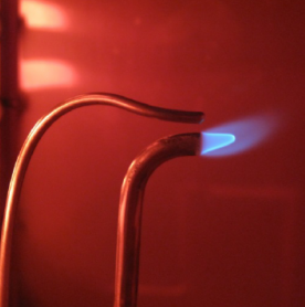
3.8.2.1The centerline of the lower burner is perpendicular to the specimen surface and located 5 mm above the exposed lower surface of the specimen. The burner port is positioned 10 mm away from the specimen surface.
3.8.2.2An electric spark igniter can be installed to ensure that the flame of the lower burner extinguishes within 3 seconds.
3.8.2.3The gas mixture ratio (methane–air) shall be adjusted so that the length of the inner flame is approximately equal to the diameter of the burner tube.
4. Data Acquisition and Measurement System
4.1A computer, data acquisition module, and PLC are used for data acquisition, processing, and control.
4.2Measure and record the maximum heat release rate during the 5-minute test period.
4.3Measure and record the total heat release within the first 2 minutes of the test.
4.4Real-time thermopile voltage.
4.5Thermopile voltage at the reference flow rate.
4.6Determination of the correction factor.
5. Installation Environment
5.1 Operating Environment:The equipment shall be installed indoors with an air-conditioning system (provided by the user) to maintain the ambient temperature at approximately (21–24)°C.
5.2The fuel gas supply shall be provided by the user and installed in a gas explosion-proof cabinet, positioned as far away from the test equipment as possible.
5.3The user shall provide an exhaust gas extraction and smoke treatment system.
5.4 Installation Space:Required installation space: Length × Width × Height: 3.5 m × 3 m × 2.5 m.
5.5 Weight:Approximately 350 kg.
Leave Message Get Price