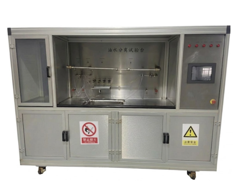
Oil-Water Separation Test Bench


1、Overview
Free water can accelerate the oxidation process of fuel and promote the formation of acids, gums, and deposits, which are collectively referred to as fuel degradation products. Water mixed with acids in the fuel can corrode ferrous and non-ferrous metals, leading to rust and corrosion of fuel system components and infrastructure, damaging fuel tanks and engine parts. Fine or coarse emulsified undissolved water may also reduce the lifespan of injection systems.
Modern fuel systems installed in passenger vehicles, heavy-duty trucks, or off-road applications require high or stable separation efficiency for all insoluble contaminants in the fuel to ensure extended service life. The oil-water separation test bench is primarily used to evaluate the oil-water separation efficiency of fuel filter products.
1.1 Design Basis
The test bench is designed in accordance with ISO 16332:2018 – “Method for evaluating the water separation efficiency of diesel engine fuel filters”, and it is used to test the water separation efficiency of fuel filters.
1.2 Test Items
(1) Water Separation Efficiency
(2) Flow vs. Pressure Drop Characteristics
1.3 Reference Standards
(1) GB/T 786.1-2021 Fluid Power Systems and Components — Graphic Symbols and Circuit Diagrams, Part 1: Graphic Symbols
(2) GB/T 3766-2015 Hydraulic Transmission — General Rules and Safety Requirements for Systems and Their Components
(3) GB/T 7935-2005 Hydraulic Components — General Technical Conditions
(4) GB/T 5226.1-2019 Safety of Machinery — Electrical Equipment of Machines, Part 1: General Requirements
(5) GB/T 5923-2010 Test Methods for Diesel Engine Fuel Filters for Automobiles
1.4 Technical Features
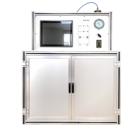
(1) The equipment adopts a closed-structure design. The test bench frame is made of industrial-grade high-strength aluminum profiles, which offer strong corrosion resistance, light weight, high strength, compact structure, attractive appearance, and ease of maintenance.
(2) The operator panel and tabletop of the test bench are made of 304 stainless steel, while the protective doors and observation side panels are made of tempered glass, providing protection while allowing real-time observation of the test samples. The top of the operating area is also made of tempered glass and equipped with a light source to ensure adequate internal illumination.
(3) The system features a user-friendly human-machine interface (HMI) with clear functions and simple operation. The test process is highly automated, displaying key filter test parameters such as pressure, differential pressure, flow rate, and temperature in real time, and allows one-button test start.
(4) The test bench is equipped with comprehensive safety protection measures, including mechanical protection and electrical alarm interlock functions. It also features phase-sequence protection, electrical interlocks, over-temperature and over-pressure protection, and liquid level safety protection, with the ability to display corresponding alarm messages for fault troubleshooting.
2、Main Technical Specifications
2.1 Working Environmental Conditions
(1) Ambient Temperature: 10℃ to 40℃
(2) Ambient Humidity: 30% to 60% RH
(3) Power Supply: AC 380V / 50Hz
2.2 Main Technical Specifications
No. | Technical Parameter | Specification | Remarks / Description |
1 | Test Fuel | Diesel 0# | - |
2 | Test Water | Purified Water | - |
3 | Test Temperature | 23 ± 2 ℃ | - |
4 | Fuel Flow Range | 50–900 L/h | - |
5 | Water Flow Range | 1.5–37.5 ml/min; 20–500 ml/min | - |
6 | System Pressure | 1000 kPa | - |
7 | System Back Pressure | ≥50 kPa | - |
8 | Product Differential Pressure | 0–100 kPa | - |
9 | Orifice Plate Differential Pressure | 0–250 kPa | - |
10 | Orifice Plate Flow Range | 0.8–25 L/min | - |
11 | Test Fuel Tank Capacity | 375 L | - |
12 | Auxiliary Fuel Tank Capacity | 50 L | - |
13 | Test Water Tank Capacity | 30 L | - |
14 | Online Laser Particle Analyzer | Measurement Range: 0.1–1000 μm Accuracy Error: ≤1% (D50 deviation, national standard sample) Testing Method: Installed in series on circulation pipeline, wet testing | - |
15 | Fully Automatic Karl Fischer Titrator | Automatic titration start, automatic sampler, manual or automatic reagent replacement | Optional |
16 | Heating Method | Silicone rubber electric heating | - |
17 | Cooling Method | Water-cooled | - |
18 | Main Test Bench Frame Material | Aluminum profiles, aluminum-plastic panels, stainless steel plates | - |
19 | Pipeline Material | 304 Stainless Steel | - |
20 | Power Supply | AC 380V / 50Hz | - |
21 | Total Power | 8 kW | - |
22 | Dimensions (L×W×H) | 3200 × 1500 × 2000 mm | - |
23 | Weight | 1000 kg | - |
3、Schematic Diagram
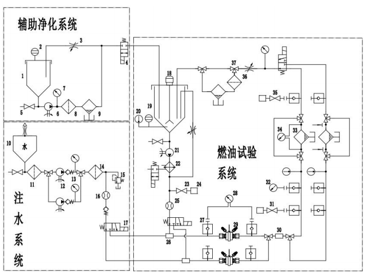
1. Auxiliary Fuel Tank
2. Level Gauge
3. Throttle Valve
4. Solenoid Valve
5. Drain Valve
6. Auxiliary Circulation Pump
7. Pressure Sensor
8. Purification Filter
9. Absolute Water Separation Filter
10. Water Tank
11. Water Filter
12. Water Injection Pump
13. Check Valve
14. Water Filter
15. Overflow Valve
16. Water Injection Flow Meter
17. Three-Way Valve
18. Agitator / Stirring Device
19. Test Fuel Tank
20. Thermometer
21. Test Pump Unit
22. Heat Exchanger
23. Baseline Sampling Valve
24. Moisture Analyzer / Water Content Measurement Device
25. Flow Meter
26. Water Injection Device
27. Quick Coupling / Quick Connector
28. Orifice Differential Pressure Meter
29. Water Emulsification Device
30. DSD Measuring Device (Droplet Size Distribution)
31. Upstream Sampling Valve
32. Upstream Pressure Gauge
33. Test Product / Device Under Test
34. Product Differential Pressure Gauge
35. Downstream Sampling Valve
36. Fuel Filter
37. Three-Way Valve
4、Main Structure and Design Description
The test bench mainly consists of six parts: the test circulation system, water injection system, test auxiliary system, online laser particle analyzer, fully automatic Karl Fischer titrator, real-time temperature control system, electrical control system, and the test bench frame.
4.1 Test Circulation System
To ensure the proper flow velocity of fuel in the test pipelines, the test circuit is designed with two loops. Each loop is equipped with an independent flow meter, water injection device, water dispersion device, and temperature sensor. Pressure, differential pressure, and upstream/downstream sampling valves are
switched between the two loops via three-way switching valves. The layout of the system, component selection, and measurement accuracy meet the relevant standards for testing equipment.
Test Pump: A stainless steel gear pump with a rated pressure of 1.45 MPa and a rated flow of 33 L/min is used. This pump features a compact structure, smooth operation, and minimal flow and pressure pulsation.
Test Fuel Tank: Made of high-quality industrial-grade stainless steel, the tank has a total volume of 420 L and an effective volume of 375 L. The cone bottom angle is designed to be no greater than 90°, ensuring
that returned fuel disperses below the liquid surface. A level monitoring device is used to monitor the fuel level and ensure stable test operation. The tank is equipped with a mechanical agitator with adjustable speed. The impeller is of the propeller type, ensuring uniform water distribution in the fuel.
Flow Meter: The system uses stainless steel gear flow meters with a flow range of 0.3–50 L/min, capable of measuring fuel flows from 50–1500 L/h. Accuracy class is 0.5, and both the body and wetted materials are made of 316 stainless steel.
Pressure and Differential Pressure Instruments:
Pressure sensors: range 0–1 MPa, accuracy class 0.5.
Product differential pressure sensors: range 0–100 kPa, accuracy class 0.25.
Orifice differential pressure sensors: range 0–250 kPa, accuracy class 0.25.
Both pressure and differential pressure measurements use self-sealing quick-connect fittings for convenient installation.
Temperature Sensors: PT100 armored resistance thermometers with a temperature range of -50–200℃, accuracy class A.
Test Pipelines: Made of high-quality industrial sanitary-grade SUS304 stainless steel, with all fittings and layout designed to eliminate dead zones to maintain turbulent flow, minimizing areas where particles could settle. The flow velocity between the water injection device and the downstream sampling point is maintained at ≥0.75 m/s.
Absolute Water Separation Filter: Professionally designed and manufactured by our company based on years of laboratory data. It can maintain the baseline water content of diesel in the test system below 30 ppm, allowing rapid system purification. The filter also has automatic drainage and alert functions. When
the water level in the purification filter reaches the warning level, the system issues an alert, and after confirmation, the water is automatically discharged from the filter housing.
4.2 Water Injection System
Test Water Tank: The system uses bottled purified water in a smart tank system for convenience, hygiene, and to minimize external dust contamination. The bottom of the tank is stainless steel conical, with an angle not exceeding 90°.
Water Injection Device: Uses an adjustable ceramic metering pump combined with an injection needle set matched to the fuel flow, forming the water injection system. The injection amount and flow rate are adjustable to meet system requirements for water volume and droplet size. The needle replacement uses a handwheel device, allowing replacement without tools.
Water Dispersion Device: Uses a standard orifice plate and orifice seat made of stainless steel, with a structure that complies with standard requirements.
Water Injection Flow Meter: Used to monitor the water injection flow and, in conjunction with the ceramic pump, enables real-time control of the water injection rate. A micro-flow stainless steel cylindrical gear flow meter is selected, with flow measurement ranges of 0.4–40 mL/min and 2–1000 mL/min, and a pressure rating of 30 MPa. Both the housing and wetted parts are made of 316 stainless steel.
Water Injection Pipelines: Made of ferrule-type sanitary stainless steel pipes.
4.3 Test Auxiliary System
To ensure stable test operation, the test sampling structure adopts a continuous flow mode (i.e., the sampling valve remains open according to the sampling flow until the test is completed). Water-containing
fuel flows directly into the auxiliary fuel tank and is purified by the auxiliary circulation pump, then returned to the test fuel tank according to the flow rate. This design avoids interference with the fuel system during sampling and simultaneously collects residual test fuel, providing great convenience for equipment operation.
4.4 Online Laser Particle Analyzer
The online laser particle analyzer is used to calibrate and measure in real time the droplet size distribution of water generated by the water emulsification device (throttle orifice) after water injection. It is a key device installed in the high-efficiency fuel filter water removal capability test line, measuring the droplet size distribution produced by the water emulsification device. The detected water droplet size directly affects the evaluation of oil-water separation efficiency.
BT-Online4 Online Laser Particle Analyzer is a key device installed on the high-efficiency fuel filter water removal capability test line, used to measure the droplet size distribution of water generated by the water emulsification device. The measured droplet size is directly related to the evaluation of oil-water separation efficiency. Compared
with laboratory laser particle analyzers, the BT-Inline4 features accurate measurement, continuous monitoring, and long-term stable operation.
Performance Specifications:
Item | Performance Specification | Item | Performance Specification |
Measurement Range | 0.1–1000 μm | Laser Source | Imported semiconductor laser |
Repeatability | ≤1% (Deviation of D50 of standard sample) | Operating System | Windows |
Accuracy Error | ≤1% (Deviation of D50 of standard sample) | Optical Detectors | 68 |
Measurement Principle | Mie, Fraunhofer | Signal Interface | RS485 |
Test Method | Installed in series on circulation pipeline, wet testing | Accuracy Verification | Standard sample + BT-802PRO |
4.5 Karl Fischer Titration System
The Karl Fischer titrator is used to measure the upstream and downstream water content of the test product. It is an essential auxiliary instrument required to complete the product testing. The measurement data directly affects the evaluation of the oil-water separation efficiency.
Technical Parameter
Category | Parameter | Specification |
Voltage | Measurement Range | −2400 mV ~ +2400 mV |
Resolution | 1.56 μV | |
Measurement Accuracy | ±0.5 mV (−2000 mV ~ +2000 mV) | |
Input Resistance | ≥ 1 × 10¹² Ω | |
Zero Drift / Bias Current | ≤ ±1 × 10⁻¹² A | |
Temperature | Sensor | Pt1000 |
Measurement Range | −150℃ ~ +250℃ | |
Resolution | ~0.002℃ | |
Measurement Accuracy | ±0.4℃ (−20.0℃ ~ +150.0℃) | |
Polarization | Ipol DC | |
Polarization Current | −200 μA ~ +200 μA, step 0.5 μA | |
Measurement Range | −2400 mV ~ +2400 mV | |
Measurement Accuracy | 0.1 mV | |
Upol DC | ||
Polarization Voltage | −2000 mV ~ +2000 mV, step 5 mV | |
Measurement Range | −200 μA ~ +200 μA | |
Measurement Accuracy | 0.01 μA | |
Other Functions | Automatic Start Titration | Yes |
Manual or Automatic Reagent Replacement | Yes | |
Titration Tube Resolution | 100000 | |
Addition Unit Volume | 2 mL, 5 mL, 10 mL, 20 mL or 50 mL | |
Automatic Sampler with OMNIS Dis-Cover Design | Optional | |
Automatic Sample Mass Import from Analytical Balance | Yes |
4.6 Real-Time Temperature Control System
The test bench is equipped with heating and cooling devices to ensure the required temperature of the test system. The test temperature can be maintained at 23 ± 2℃, meeting the requirements of relevant standards.
4.7 Electrical Control System
The electrical control system mainly consists of hardware and software components. The system hardware uses a Siemens PLC combined with a touch-screen integrated controller. Internal electrical components are from Schneider or equivalent brands, effectively ensuring reliable equipment operation.
The operation software interface is simple and intuitive, capable of automatic operation based on set parameters, and can display the system working status in real time. The system supports both automatic and manual control modes. Once parameters are set, the test can be started with one-button operation. If the measured upstream water content does not meet test requirements, the water injection pump frequency can be manually adjusted for fine-tuning.
The control system is equipped with abnormal alarm and safety protection functions. When an abnormal condition occurs, the system displays common error causes to facilitate troubleshooting.
4.8 Test Bench Frame
The test bench frame is made of high-strength industrial aluminum profiles, with four industrial casters (each bearing up to 500 kg) with leveling feet, allowing both flexible movement and secure support.
The test panels and operation tabletop are made of stainless steel, with laser-etched markings that are clear, aesthetically pleasing, and permanent. The test bench incorporates transparent tempered glass safety protection, allowing easy observation of the test sample while effectively preventing fuel splashes from harming operators.
The top of the bench uses tempered glass combined with LED lighting to provide an energy-saving and environmentally friendly lighting solution, maximizing illumination for the test area.
4.9 Safety
(1) The equipment features overpressure, over-temperature, overload, leakage, and liquid level protection, as well as abnormal condition alarms and self-protection functions to prevent accidents
(2) and ensure safe operation. The program interface displays alarm information for timely troubleshooting. During operation, the system monitors test parameters in real time, and if any abnormal condition occurs, the system can automatically stop operation.
(3) The equipment exterior is equipped with signal devices or warning signs to alert operators. Protective doors surround the bench, and electrical interlocks prevent accidents due to misuse, ensuring operator safety.
(4) An emergency stop button is installed on the front operation panel to allow immediate shutdown in case of unexpected situations, minimizing damage and ensuring operator safety.
(5) The bottom of the equipment features a removable drip tray to prevent environmental contamination caused by spills, leaks, or drips.
Leave Message Get Price