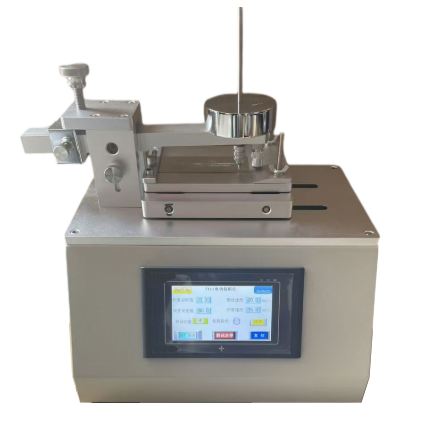
Surface Scratch Resistance Tester
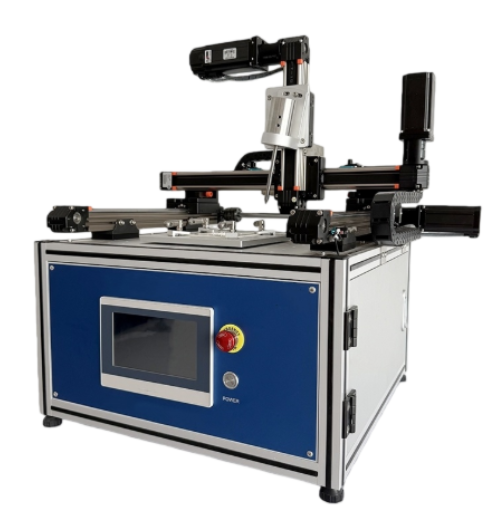


Surface Scratch Resistance Tester is used to conduct scratch tests on solid insulating accessible parts or printed circuit boards in household appliances, information technology equipment, and similar products. By applying standardized scratches to the specimen surface under specified conditions, it verifies the material's puncture resistance and insulation safety under mechanical stress to meet relevant safety standards.
Application
This equipment is suitable for testing the surface scratch resistance of the following materials and products:
- Scratch testing of accessible solid insulating parts or printed circuit boards in household appliances and similar products to ensure materials possess sufficient strength against penetration by sharp tools
- Enclosures and structural components of information technology equipment and office equipment
- Printed circuit boards (PCBs) and their insulating substrates
- Non-metallic materials such as plastics, coatings, and insulating layers
- Insulating separation zones in electrical products subjected to significant potential gradients
Applicable to product type testing, design verification, and safety performance evaluation.
Standards
GB4706.1-2005 “Safety of Household and Similar Electrical Appliances - Part 1: General Requirements” Clause 21.2
GB4943.1-2011 “Safety of Information Technology Equipment - Part 1: General Requirements” Clause 2.10.8.4
IEC60335-1:2004 “Household and similar electrical appliances—Safety—Part 1: General requirements” clause 21.2
IEC60950-1:2005 “Information technology equipment—Safety—Part 1: General requirements” clause 2.10.8.4
Parameters
| Parameter Name | Parameter Data |
|---|---|
| Power Supply Voltage | AC 220V, 50Hz |
| Test Station | Single Station |
| Control Method | PLC electrical control, 7-inch color touch screen |
| Driving Method | Stepping Motor |
| Scratching Needle Head Radius | R0.25 ±0.02 mm |
| Steel Needle Vertex Angle | 40° |
| Scratching Speed | 20 ±5 mm/s, Presettable |
| Scratching Pressure | 10 N ±0.5 N |
| Scratching Spacing | 0–50 mm, Presettable |
| Scratching Angle | 80–85° (Fixture Fixed) |
| Sample Tray | Rotatable by 90°, Multi-mounting Hole Structure |
Features
Formed ball screw and linear guide structure ensures smooth motion and high positioning accuracy
Hardened steel stylus design with tip geometry meeting standard requirements
PLC + touchscreen control with preset parameters and intuitive operation
Supports independent multi-axis speed settings to meet standard scratch speed requirements
Sample tray capable of 90° rotation for cross-directional scratch testing
Compact structure with excellent overall stability, suitable for long-term laboratory use
Accessories
| Name | Quantity | Remarks |
|---|---|---|
| Scratch Resistance Tester | 1 unit | Main Unit |
| Scratching Needle | 1 piece | Hardened Steel Needle |
| Hexagon Wrench | 1 set | For Installation and Adjustment |
| Sample Pressure Plate | 4 pieces | For Sample Fixation |
Test Principle
The coating scratch resistance test employs a hardened steel needle for scratching. The needle tip shall be tapered with a 40° apex angle and shall be rounded and polished with a radius of 0.25mm ± 0.02mm. The scratch traverses five pairs of conductive sections, including the intermediate gaps. These gaps represent the areas subjected to the highest potential gradient during testing. When performing the scratch test, maintain the needle at an angle of 80-85° to the horizontal plane and apply the scratch at a speed of 20 mm/s ± 5 mm/s. An appropriate load shall be applied to the steel needle to exert a force of 10 N ± 0.5 N along its axial direction. Each scratch shall be spaced at least 5 mm apart and shall be at least 5 mm from the sample edge.
Touchscreen Interface Functions
1. Power on the device. The display shows the equipment name and company information. Press to enter the system and proceed to the control screen.
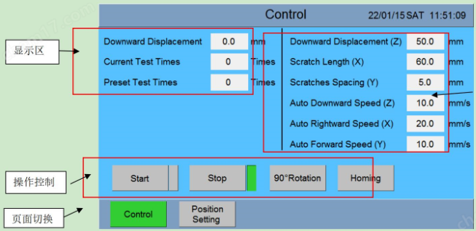
2. Control Screen Overview
【Automatic Downward Speed (Z)】: Controls the vertical movement speed, unit: mm/s.
【Automatic Rightward Speed (Y)】: Controls the lateral movement speed, unit: mm/s.
【Automatic Forward Speed (X)】: Controls the forward movement speed, unit: mm/s.
【Downward Displacement (Z)】: Vertical travel distance of the scratch steel needle, in mm.
【Scratch Length (Y)】: Horizontal travel distance of the scratch steel needle, in mm.
【Scratch Spacing (X)】: Vertical travel distance of the scratch steel needle, in mm.
【Scraper Position】: Current vertical position of the scratch steel needle.
【Test Count】: Current scratch count of the steel needle.
【Total Scratches】: Total number of tests performed by the steel needle.
【Start】: Initiates device operation.
【90° Rotation】: Selects whether to perform the scratch test after a 90° rotation.
【Return to Origin】: Resets the device to its initial state.
3. Overview of the Scratch Settings Screen
3.1. Z-Axis Manual Speed Setting: Set the Z-axis manual speed in mm/s. Press Upward or Downward on the right to manually move up or down.
3.2. Y-Axis Manual Speed Setting: Set the Y-axis manual speed in mm/s. Press Leftward or Rightward on the right to manually move left or right.
3.3. X-Axis Manual Speed Setting: Set the X-axis manual speed in mm/s. Press the Backward or Forward buttons on the right to manually move backward or forward.
3.4. Specimen Turntable Control: Enables clockwise or counterclockwise rotation of the turntable.
3.5. Scratch Starting Point Settings: Press [Set Center Point] to set the center scratch point. Press [Set Arbitrary Starting Point] to set an arbitrary starting point. When setting an arbitrary starting point, the scratch needle must first move to that position before the arbitrary starting point button can be pressed.
Test Procedures
1. Sample Installation
Center the product on the test bench. If oversized, modify it for easier installation and secure it tightly with the clamping plate. For thin samples under 2mm, press the sample against the flat surface of the clamping plate. 2. Parameter Settings
(1) Starting Point Selection (Choose one based on specimen conditions):
a. 【Set Center Point】: Select this to use the turntable center as the midpoint. Scratch length will be symmetrical left/right from this center, and scratch count will be symmetrical up/down from this center. Example: Scratch length 50. scratch spacing 5. scratch count 2 → Starting coordinates (X-25. Y+5).
b. 【Arbitrary Start Point】: Manually advance the steel needle forward and to the right. Observe its actual position and press this key to confirm the current location as the starting point.
(2) Scratch Vertical Position: In manual mode, observe the needle position via vertical movement. When the scratching needle is lifted off the support surface by the specimen, return to the control interface and input the displayed 【Scraper Position】 value into the 【Downward Position】 setting. If the 【Scraper Position】 is 35mm, enter 35 in 【Downward Displacement】.
(3) Preset vertical, horizontal, and front/back motor speeds. Note: The standard requires horizontal motor speed to be 20mm/s ± 5mm/s.
(4) Preset scratch length according to the standard. Ensure that after rotating 90°, scratches do not extend beyond the specimen edges or intersect. Adjust scratch length and starting point as needed to achieve this.
(5) Preset the scratch spacing to ensure sufficient separation between scratches to prevent interference.
(6) Preset the number of scratches. For 90° scratch tests, select the 90° rotation option.
3. Operation and Running
After configuring all parameters, press [Return to Origin], then press [Start] to begin the test.
The steel needle trajectory is: absolute zero point → starting point (manually selected) → scratch needle descends to downward displacement value → rightward scratch length → return to height zero point → retract to starting point → forward scratch spacing → continue to next cycle. After reaching the preset number of cycles, the machine automatically stops and returns to the starting point.
FAQ
1. What materials can you test with this equipment?
You can test plastics, insulating coatings, PCB substrates, and other non-metallic insulating materials used in electrical products.
2. Why is the scratch angle fixed at 80–85°?
This angle simulates worst-case mechanical stress conditions defined by safety standards to evaluate insulation integrity under penetration risk.
3. How do you ensure repeatable test results?
Repeatability is achieved through precise motor control, standardized needle geometry, fixed scratch angle, and PLC-controlled parameters.
4. Can you perform cross-directional scratch tests?
Yes, the 90° rotatable sample table allows perpendicular scratch patterns on the same specimen.
5. How often should the scratching needle be replaced?
You should replace the needle once tip wear affects the specified radius or when test results become inconsistent.
6. Is the tester suitable for certification testing?
Yes, it is designed specifically to meet the requirements of IEC and GB safety standards used for certification and compliance testing.
Leave Message Get Price