Tapered Bearing Fatigue and Wear Testing Machine
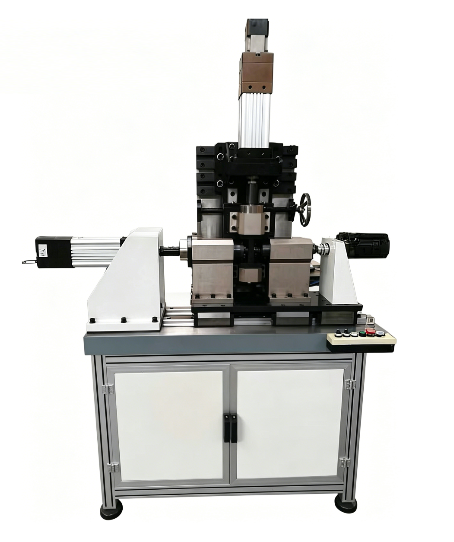


The tapered bearing fatigue and wear testing machine is a dedicated test equipment designed and manufactured according to user-supplied technical requirements. The system adopts a servo control system. Axial and radial loading are both driven by electric cylinders. Rotation is driven by a servo motor. The electrical system is controlled by a computer-based servo control system. The test software is developed in the Windows platform using Visual Studio (VS) programming language. The system can perform parameter setting, data acquisition and processing, real-time interface display, and curve plotting functions.
Application
This equipment is used for fatigue life testing, wear performance evaluation, torque monitoring, and durability validation of tapered roller bearings. It is widely applied in automotive engineering, rail transportation systems, heavy-duty machinery manufacturing, aerospace bearing development, and industrial research laboratories. The machine is suitable for product validation, quality inspection, and long-term reliability studies under complex working conditions.
Standards
(1) User-defined technical specifications and test requirements
(2) Relevant bearing design and fatigue evaluation engineering documents
(3) ISO 281 (Rolling bearings – Dynamic load ratings and rating life)
(4) ISO 76 (Static load ratings for rolling bearings)
(5) GB/T 307.1 (Rolling bearings – General technical requirements)
(6) ASTM D4172 (Wear preventive characteristics of lubricating fluids, reference method)
Designed according to user-provided test requirements and relevant technical documentation.
Working Principle
The rotary (or oscillating) drive unit is installed on the base platform. It consists of a servo motor, gearbox, bearing support, coupling, torque sensor, etc.
The servo motor is equipped with an optical encoder for measuring and controlling rotational angle. The bearing support is used to install and support the test bearing, torque sensor, and motor. The inner bore shaft of the test bearing is connected to the rotary system through a universal coupling.
To eliminate the influence of misalignment during radial loading, a telescopic spline shaft is integrated into the rotary axis. A torque sensor is installed in the rotary system to measure torque.
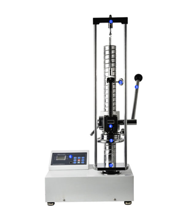
The axial loading system consists of an electric loading cylinder, force sensor, loading linkage, and bearing support frame. The electric cylinder drives a loading frame supported by dual linear guide rails. Load is applied to the test bearing through a force sensor and linkage system.
To ensure smooth and impact-free loading, a set of double-stacked disc springs is integrated into the loading system. The load is transmitted to the test bearing through the disc springs. A coaxial swingable bearing seat is adopted to eliminate angular deviation during testing.
The radial loading system consists of an electric cylinder, force sensor, and loading bearing support. The cylinder is hinged to the base and applies radial load through the force sensor and support assembly. The encoder of the servo motor is used to measure displacement, and the deviation angle is calculated accordingly.
The test bearing fixture consists of a split bearing housing and replaceable test tooling. According to different bearing sizes, corresponding fixtures are selected and installed in the housing, then fixed by bolts. The test shaft is connected to the axial loading mechanism via bolts, and connected to the radial loading system and rotary system through a shaft and coupling, ensuring both easy installation and stable loading performance.
Main Technical Specifications
Item | Parameter | Value |
1 | Axial & radial loading mode | Alternating load (reversible direction) |
2 | Axial loading capacity | 15 kN |
3 | Radial loading capacity | 30 kN |
4 | Sensor accuracy | ≤ ±1% (automatic range switching) |
5 | Swing angle range | ±360° |
6 | Angle measurement accuracy | 0.1° |
7 | Control mode | Angle / Force |
8 | Operating frequency | 0–1.5 Hz (based on ±60° swing angle) |
9 | Maximum bearing outer diameter | ≤ φ150 mm (customizable) |
10 | Maximum rotational speed | 0–3000 rpm |
11 | Test program reference | Reference figure (final test procedure customized according to user requirements)
|
Technical Documents
(1) General assembly drawing – 1 set
(2) Wear parts, spare parts, and fixture drawings – 1 set
(3) Electrical schematic, servo control schematic, and software system manual – 1 set
(4) Operation manual – 1 copy
(5) Packing list – 1 copy
(6) Certificates of main purchased components – 1 set
FAQ
(1) What is this product?
The Tapered Bearing Fatigue and Wear Testing Machine is a servo-controlled testing system used to evaluate fatigue life and wear performance of tapered bearings under combined mechanical loads.
(2) What is this product used for?
It is used for simulating real operating conditions of bearings to assess durability, torque behavior, and fatigue failure characteristics in engineering applications.
(3) What is the working principle of this product?
The system uses servo motors and electric cylinders to apply rotational, axial, and radial loads while sensors collect force, torque, and displacement data for analysis.
(4) Why is this product important?
It ensures accurate prediction of bearing lifespan and performance, reducing failure risks and improving reliability in critical mechanical systems.
(5) What industries is this product suitable for?
It is widely used in automotive, rail transit, aerospace, heavy machinery manufacturing, and bearing research laboratories.
Leave Message Get Price