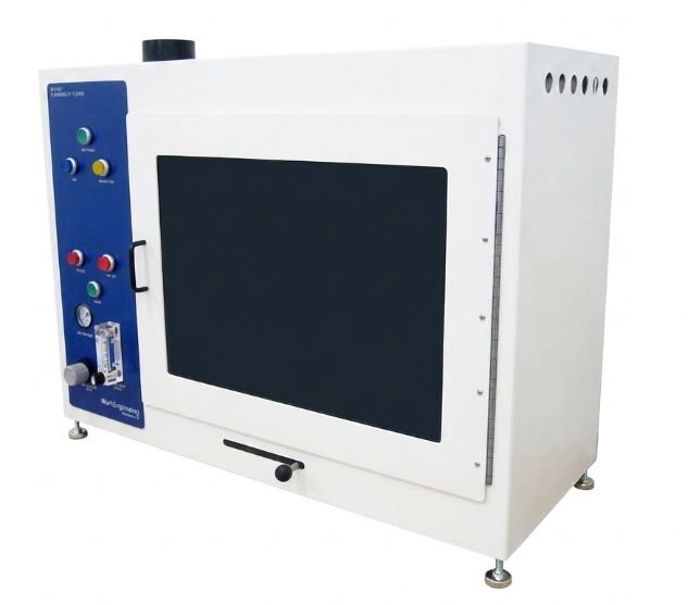
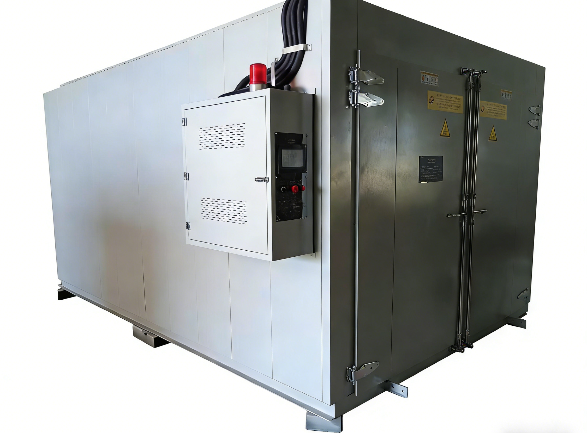
Fire Resistance Cable Circuit Integrity Test Apparatus


1. Scope of Application:
1.1 Applicable to fire-resistant cables with rated voltage not exceeding 600/1000V and outer diameter ≤20 mm, to assess whether circuit integrity is maintained under fire conditions.
1.2 This tester includes fire resistance test, water spray fire resistance test, and mechanical fire resistance test.
2. Standards Compliance:
2.1 Complies with BS 6387:2013 Test method for resistance to fire of cables required to maintain circuit integrity under fire conditions.
2.2 Complies with BS 8491 Method for assessment of fire integrity of large diameter power cables for use as components in smoke and heat control systems and other specific fire safety systems.
3. Main Parameters:
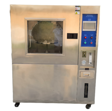
3.1 Fire Resistance Test:
3.1.1 Sample Support Device:
The sample support frame consists of three support rings. The inner diameter of each metal ring is approximately 150 mm, made of round steel bars with a diameter of (10 ± 2) mm. During the test, the sample is placed on the rings. One end is fixed to prevent movement, while the other end is supported to allow longitudinal movement due to thermal expansion.
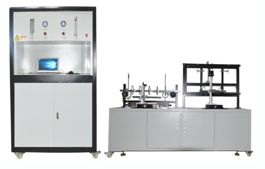
3.1.2 Continuity Checking Device:
3.1.2.1 During the test, current for continuity checking passes through all conductors of the cable. This current is supplied by a three-phase star-connected transformer with sufficient capacity to maintain the required test voltage at maximum allowable leakage current. At the other end of the sample, each conductor or group of conductors is connected to an appropriate load and indicating device (such as lamps), forming a current circuit (a stabilizing resistor may be added if necessary). Under test voltage, the current through each conductor or group is 0.25 A.
3.1.2.2 Fuse:
2 A fuse in accordance with IEC 60269-3:2010, fuse types A–D, model DII.
3.1.2.3 Test Voltage (phase voltage):
0–1000 V continuously adjustable.
3.1.3 Heat Source:
Ribbon-type propane gas burner with Venturi mixer, nominal flame length 610 mm. The nominal width of the flame surface is 15 mm, with three staggered rows of drilled holes of nominal diameter 1.32 mm and center spacing of 3.2 mm.
3.1.4 Temperature Measurement:
Measured using a Φ1.5 mm mineral-insulated stainless steel sheathed K-type thermocouple (in accordance with BS EN 60584-1). The burner is positioned approximately 45 mm horizontally from the thermocouple and 75 mm vertically below the thermocouple centerline. Ignite the burner and adjust gas and air supply until the flame temperature stabilizes at 950°C ± 40°C for at least 5 minutes. Record gas and air flow values, then extinguish the burner.
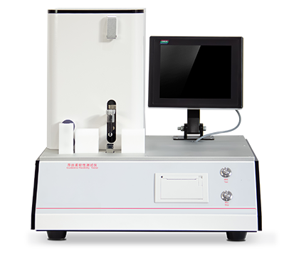
3.2 Water Spray Fire Resistance Test:
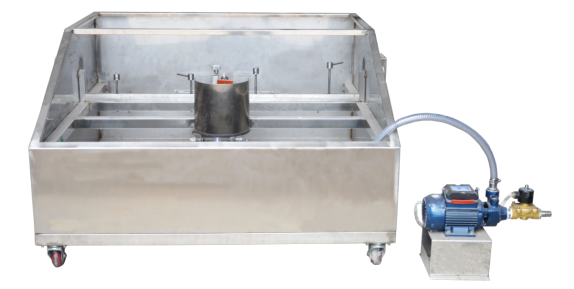
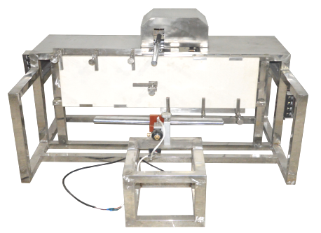
Water Spray Fire Resistance Test Bench (Spray Device)
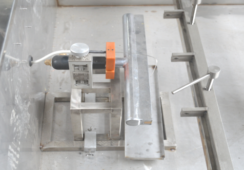
Figure 3 Fire Resistance Section of the Water Spray Fire Test Bench
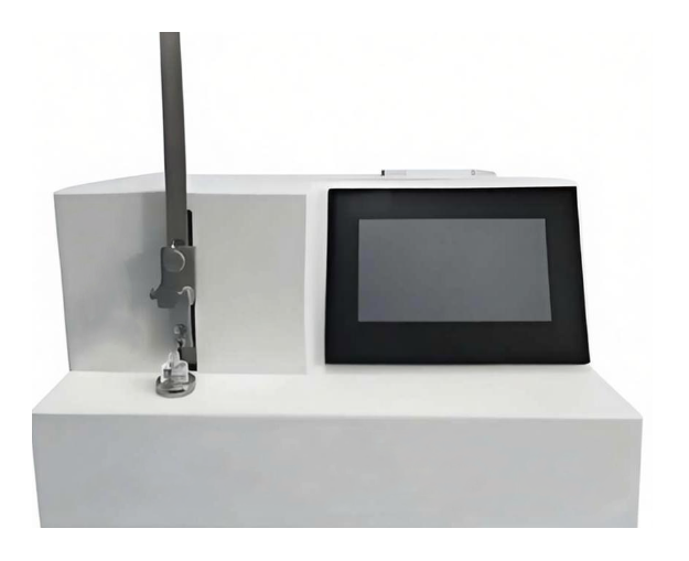
3.2.1 Sample Support Device:
The test sample is connected via copper clamps to a metal support consisting of two steel bars with dimensions of 25 mm ± 1 mm in width, 1150 mm ± 25 mm in length, and 5.5 mm ± 1 mm in thickness. The spacing between clamps is 200 mm ± 10 mm. The assembly with the cable is supported within a test frame, and the frame is grounded.
3.2.2 Continuity Checking Device:
3.2.2.1 During the test, current for continuity checking passes through all conductors of the cable. This current is supplied by a three-phase star-connected transformer with sufficient capacity to maintain the required test voltage at maximum allowable leakage current. At the other end of the sample, each conductor or group of conductors is connected to an appropriate load and indicating device (such as lamps), forming a current circuit (a stabilizing resistor may be added if necessary). Under test voltage, the current through each conductor or group is 0.25 A.
3.2.2.2 Fuse:
2 A fuse in accordance with IEC 60269-3:2010, fuse types A–D, model DII.
3.2.2.3 Test Voltage:
0–1000 V continuously adjustable (line voltage 1000 V, phase voltage 600 V).
3.2.3 Heat Source:
Ribbon-type propane gas burner with Venturi mixer, nominal flame length 500 mm. The nominal width of the flame surface is 10 mm, with three staggered rows of drilled holes of nominal diameter 1.32 mm and center spacing of 3.2 mm.
3.2.4 Temperature Measurement:
Measured using a Φ1.5 mm mineral-insulated stainless steel sheathed K-type thermocouple (in accordance with BS EN 60584-1). During the test, the thermocouple is placed at the lower surface of the cable sample. Ignite the burner and adjust gas and air supply until the flame temperature stabilizes at 650°C ± 40°C for at least 5 minutes. Record gas and air flow values, then extinguish the burner.
3.2.5 Water Spray:
The spray head is fixed to the test frame and positioned centrally relative to the burner assembly. Water is sprayed at a rate between 0.25 L/m²/s and 0.30 L/m²/s. The flow rate is measured using a collection tray of 400 mm ± 5 mm in length and 100 mm ± 5 mm in width. The tray should be placed at the center of the sample, with its long axis aligned with the cable axis.
3.3 Mechanical Shock and Fire Resistance Test:
3.3.1 Mechanical Shock Device:
The cable is fixed on a vertical wall and secured to a steel plate using heat-resistant and non-combustible materials.
3.3.2 Wall and Its Installation:
The wall is made of heat-resistant and flame-retardant materials and is fixed to two horizontal steel beams, one at the top and the other at the bottom of the panel. The panel is approximately 900 mm long, 300 mm wide, and 9 mm thick, and the total mass of the wall (i.e., panel plus supporting frame) is 10 ± 2 kg. Each steel beam is approximately 1 m long and made of 25 mm square steel tubing. If ballast is required, it shall be placed inside the steel beams. The upper steel beam must be fixed to the panel so that its upper surface is flush with the top edge of the panel. Each steel beam and the outer edge of the panel has a horizontal hole, the exact position of which is determined by the requirements of specific support pads and the
supporting frame. The wall is bonded to the frame by four rubber bushings, each approximately 32 mm in diameter and 20 mm thick.
3.3.3 Impact Generating Device:
The impact generating device consists of a low-carbon steel round bar with a diameter of (25 ± 0.1 mm) and a length of (600 ± 5 mm). The bar rotates freely around an axis parallel to the test ladder, located at the same horizontal level as (200 ± 5 mm) above the upper edge of the test ladder. This axis divides the bar into two unequal lengths, namely (400 ± 5 mm) and approximately 200 mm, with the longer portion striking the test ladder. The bar falls under its own weight from an angle of 60° to the horizontal plane onto the central position of the wall every 30 s ± 2 s.
3.3.4 Continuity Checking Device:
3.3.4.1 During the test, current for continuity checking passes through all conductors of the cable. This current is supplied by a three-phase star-connected transformer with sufficient capacity to maintain the required test voltage at the maximum allowable leakage current. At the other end of the sample, each conductor or group of conductors is connected to an appropriate load and indicating device (such as lamps), forming a current circuit (a stabilizing resistor may be added if necessary). Under test voltage, the current through each conductor or group is 0.25 A.
3.3.4.2 Fuse:
2 A fuse in accordance with IEC 60269-3:2010, fuse types A–D, model DII.
3.3.4.3 Test Voltage (phase voltage):
0–1000 V continuously adjustable.
3.3.5 Heat Source:
Ribbon-type propane gas burner with Venturi mixer, nominal flame length 500 mm. The nominal width of the flame surface is 10 mm, with three staggered rows of drilled holes of nominal diameter 1.32 mm and center spacing of 3.2 mm.
3.3.6 Temperature Measurement:
Measured using a Φ1.5 mm mineral-insulated stainless steel sheathed K-type thermocouple (in accordance with BS EN 60584-1). The thermocouple is installed on a non-combustible board to measure the burner flame temperature, passing through the board so that the tip of the thermocouple protrudes 8 mm to 10 mm. Ignite the burner and adjust gas and air supply until the flame temperature stabilizes at 950°C ± 40°C for at least 5 minutes. Record the gas and air flow values, then extinguish the burner.
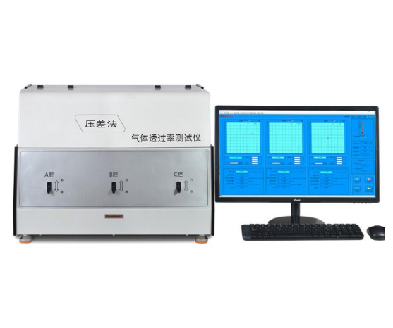
4. Control System:
4.1 Computer-controlled.
4.2 The equipment is equipped with the following safety protection devices: power overload, short circuit protection, and control circuit overload protection. It includes power-off, short circuit, alarm, and indication of breakdown current: 3 A (after sample breakdown, automatic alarm and cut-off of power supply and gas supply system).
4.3 All components are of high quality to ensure high system performance and fast operation, featuring advanced design. The system adopts fully automatic control for testing, enabling automatic detection control and completion of test procedures. It has a user-friendly interface, ensuring faster and more accurate testing. It can automatically generate temperature control curves and output reports, as well as perform data acquisition and print test results.
5. Environmental Conditions:
5.1 The ground shall be flat and well-ventilated, free of flammable, explosive, and corrosive gases and dust.
5.2 No strong electromagnetic radiation sources nearby.
5.3 Adequate maintenance space shall be reserved around the equipment.
5.4 Temperature: 5°C to 30°C.
5.5 Atmospheric pressure: 86–106 kPa.
5.6 AC 380 V / 50 Hz.
5.7 Allowable voltage fluctuation range: 380 V ± 10%.
5.8 Allowable frequency fluctuation range: 50 Hz ± 1%.
5.9 The user shall configure an air and power switch with appropriate capacity at the installation site, and the switch must be dedicated exclusively to this equipment.
5.10 When the equipment is not in operation, the ambient temperature shall be maintained within +0 to 45°C, and the vibration combustion device shall be placed in the combustion chamber.
FAQ
1.What is a Fire Resistance Cable Circuit Integrity Test Apparatus?
A Fire Resistance Cable Circuit Integrity Test Apparatus is a specialized device used to evaluate and ensure that electrical cables maintain their integrity during exposure to high temperatures and fire. This apparatus simulates fire conditions to test how well the cables can continue to function and provide power or communication during a fire scenario.
2.Why is cable circuit integrity testing important?
Testing cable circuit integrity is crucial for ensuring safety in buildings and critical infrastructure. In the event of a fire, cables must remain operational to support emergency systems, alarms, and lighting. This testing helps to prevent complete system failure, which could jeopardize lives and property.
3.What standards govern fire resistance cable testing?
Fire resistance cable testing is governed by several international standards, including IEC 60331 and BS 8434. These standards outline the methodology and performance criteria for testing the integrity of electrical cables under fire conditions, ensuring that cables can function adequately during emergencies.
4.How does the testing process work?
The testing process involves subjecting the cables to a controlled fire scenario, where heat and flames are applied for a specified duration. The apparatus monitors various performance indicators, such as the ability to maintain electrical continuity and structural integrity, to determine if the cables meet the required standards.
5.What types of cables can be tested?
The Fire Resistance Cable Circuit Integrity Test Apparatus can be used to test a wide variety of cables, including power cables, control cables, and communication cables. Cables designed for use in fire-prone areas, such as emergency lighting or alarm systems, are particularly critical for this type of testing.
Leave Message Get Price