PV Light Induced Degradation (LID) Testing Chamber
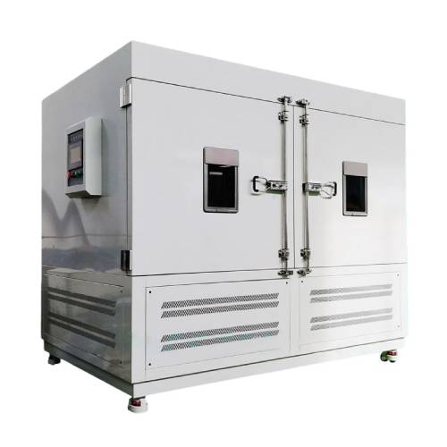


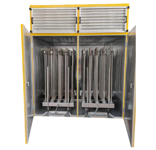
The Light Decay Test Chamber is a high-precision indoor exposure system specifically engineered for the performance degradation analysis of solar modules and cells. By utilizing high-intensity xenon lamps as a simulated solar source, the chamber replicates prolonged sunlight exposure to evaluate light-induced degradation (LID), perform hot-spot endurance tests, and facilitate pre-conditioning processes. With a light source that meets or exceeds Class BBB standards for spectral match, spatial uniformity, and temporal stability, this system allows you to achieve laboratory-grade accuracy in assessing the long-term efficiency of photovoltaic products.
Applications
The Light Decay Test Chamber is designed as an indoor exposure system, primarily used for standard module and cell degradation testing, module hot spot testing, and module pre-treatment. Spectral matching, irradiance uniformity, and irradiance stability meet at least BBB-grade standards.
This system comprises a light source system, temperature control system, module support structure, light source control system, and irradiance monitoring system. Utilizing xenon lamps as the light source, the irradiance across the exposure surface can be steplessly adjusted between 400 and 1200 W/m².
Standards
IEC 61215: Terrestrial photovoltaic (PV) modules—Design qualification and type approval (Specifically the Light-Induced Degradation and Hot-spot tests).
IEC 60904-9: Photovoltaic devices—Part 9: Classification of solar simulator characteristics (Meeting BBB or higher standards).
GB/T 9535: Ground-based silicon solar photovoltaic modules—Design qualification and type approval.
IEC 61646: Thin-film terrestrial photovoltaic (PV) modules—Design qualification and type approval (Stabilization phases).
Features
1. Utilizes a xenon lamp as the light source, providing an irradiation area of 1m x 2m, with over-temperature power-off protection.
2. Records irradiance, chamber temperature, and provides both instantaneous irradiance and cumulative irradiation data.
3. Chamber employs air cooling, with internal temperature controllable within 20°C to 50°C.
Parameters
| Category | Item | Specifications |
|---|---|---|
| 1. Xenon Lamp Parameters | Dimensions | 200*40mm |
| Power | 1800W | |
| Operating Voltage | 180VAC | |
| Lamp Life | 700h (with cumulative timing function for lamp tube) | |
| 2. Chamber Structure | Construction | Welded integral structure |
| Outer Wall Material | Galvanized steel sheet (spray-painted) | |
| Inner Wall Material | SUS304 stainless steel sheet | |
| Insulation Material | Glass fiber or polyurethane foam material | |
| Accessories | Equipped with standard viewport: 1 multi-layer glass window (with work light) | |
| 3. Radiometer | Spectral Range | 300 ~ 3000nm |
| Irradiance Range | 0 ~ 2000W/m² | |
| Annual Stability | 2% | |
| Azimuth Response Error | 5% | |
| Non-linearity | 2% | |
| Temperature Error | 2% (-10°C ~ 40°C) | |
| 4. Temperature | Sensor Type | PT100 |
| Measurement Range | -200 ~ 500°C | |
| Test Accuracy | ±1°C | |
| Resolution | 0.1°C | |
| Probe Diameter | Φ5mm | |
| Installation Method | Fixed with movable screws | |
| Probe Length | 5cm | |
| Resistance Change | 0.3851Ω/°C | |
| Lead Connection Method | Three-wire type | |
| Sleeve Material | Stainless steel 304 |
Accessories
1.High-Intensity Xenon Lamp Array: Core light source with a 700-hour rated lifespan and cumulative timer.
2.Slide-in Sample Carrier: Aluminum profile bracket with rollers for easy loading/unloading of heavy modules.
3.Calibrated Pyranometer: High-stability sensor for real-time irradiance monitoring.
Test Procedures
1. Site: Level ground with good ventilation, free from flammable, explosive, or corrosive gases and dust. No strong electromagnetic radiation sources nearby. Adequate maintenance space around equipment.
2. Environmental Conditions:
Temperature: 5°C to 35°C
Relative Humidity: ≤85% RH
Atmospheric Pressure: 86–106 kPa
3. Power Supply:
AC 380V, three-phase four-wire + protective earth wire;
Voltage tolerance range: AC (1±10%) 380V
Allowable frequency fluctuation range: (1±1%) 50Hz
Protective earth grounding resistance must be less than 4Ω; TN-S or TT power supply system
Users must install an appropriately rated air or power circuit breaker at the installation site, dedicated exclusively to this equipment
4. Storage Environment Requirements:
When the equipment is not in operation, the ambient temperature must be maintained between +5°C and 35°C.
FAQ
1.What is the purpose of light-induced degradation testing in photovoltaic modules?
Light-induced degradation testing allows you to evaluate early-stage power loss caused by light exposure, particularly in crystalline silicon modules. This test helps predict initial performance drop and long-term energy yield.
2.How does this chamber meet Class BBB solar simulator requirements?
The xenon lamp system is designed to provide appropriate spectral match, spatial uniformity, and temporal stability, meeting or exceeding Class BBB criteria defined in IEC 60904-9.
3.Can full-size photovoltaic modules be tested in this chamber?
Yes. The irradiation area of 1 m by 2 m and the reinforced sample carrier are suitable for testing standard full-size photovoltaic modules.
4.How is sample temperature controlled during high-irradiance testing?
An air-cooled temperature control system regulates the chamber environment, while infrared temperature monitoring helps ensure that the module surface temperature remains within the specified control range.
5.Can irradiance be adjusted to simulate different sunlight intensities?
Yes. The system supports stepless irradiance adjustment from 400 to 1200 W per square meter, allowing you to simulate various sunlight exposure conditions.
6.How do you ensure repeatability of long-duration light exposure tests?
Repeatability is ensured through stable light source control, continuous irradiance monitoring, precise temperature regulation, and routine calibration of all measurement systems.
Leave Message Get Price