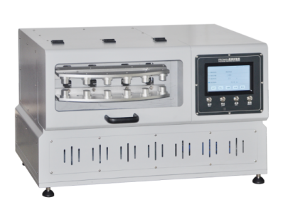
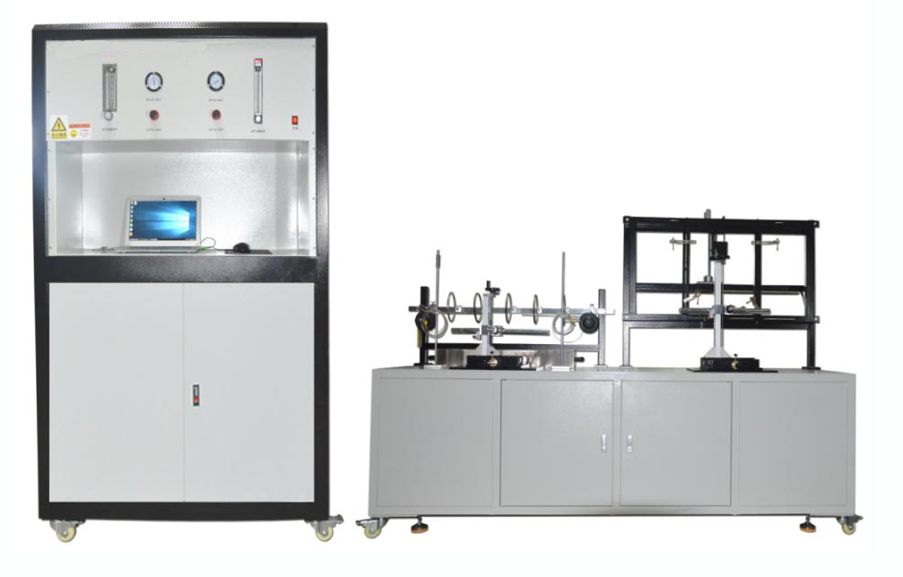
Test System for the characterisation of the air flow velocity profile of components
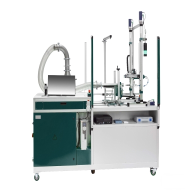


The Test System for the characterisation of the air flow velocity profile of components is designed to measure air flow velocities and turbulence in various flowed-through units, such as tubes, ducts, and filters. It allows the determination of optimal positions for flow measurement devices (e.g., MAF sensors) and provides precise data for validating computational flow simulations. The system enables accurate measurement over a wide range of flow rates and velocities, ensuring reproducible and high-quality results.
Application
(1) Development and optimisation of filter housings, air-ducting elements, and other airflow components.
(2) Identification of optimal positions for mass air flow (MAF) sensors and other measurement devices within flow-through components.
(3) Validation and comparison of computational fluid dynamics (CFD) models with experimental flow data.
(4) Measurement of airflow velocity profiles and turbulence for HVAC components, automotive filters, and industrial ducts.
(5) R&D studies to improve pressure drop characteristics and airflow uniformity in engineered components.
Standards
(1) ISO 5167 — Measurement of fluid flow by means of pressure differential devices.
(2) ISO 12103 — Test dust and air filter media measurement methods (related airflow measurement guidance).
(3) EN 779 / ISO 16890 — Air filter flow characterization for general ventilation (applicable when flow through filter media is tested).
Features
(1) Wide flow rate range: 20 – 900 m³/h (expandable to 1200 m³/h).
(2) Air velocity measurement range from 1 to 40 m/s.
(3) Accurate turbulence detection at the outlet of components under test.
(4) Automated traversing system for scanning velocity fields across a measurement plane.
(5) High-resolution data acquisition with real-time graphic display.
(6) Suitable for a variety of test components, including tubes, ducts, filter housings, and flow elements.
(7) Enables model validation and design optimization for both R&D and production purposes.
Parameters
| Parameter | Unit | Value |
|---|---|---|
| Test flow rate | m³/h | 20 – 900 (expandable to 1200) |
| Air flow velocity | m/s | 1 – 40 |
| Test specimen dimensions | mm | max. 485 × 600 |
| Differential pressure of test specimen | Pa | – |
| System dimensions (W × H × D) | mm | 2500 × 2660 × 1300 |
| Weight | kg | approx. 550 |
Test Procedures
(1) Install the component under test in the test section.
(2) Set the desired airflow rate using the system’s flow control.
(3) Activate the traversing device and begin automatic scanning of the measurement plane.
(4) Record airflow velocity and turbulence data using the hot-wire anemometer.
(5) Analyze velocity profiles to determine optimal sensor placement or to validate CFD simulations.
(6) Save and export data for further analysis or reporting.
Maintenance Information
(1) Periodically clean the air flow path and hot-wire sensors to prevent dust buildup.
(2) Calibrate the hot-wire anemometer according to the manufacturer’s recommendations.
(3) Check the traversing system and ensure smooth and precise movement.
(4) Inspect electrical and pneumatic connections regularly.
(5) Verify data acquisition software and system sensors are operating correctly before testing.
FAQ
(1) What is this product?
– A test system designed to measure air flow velocity profiles and turbulence in flowed-through components such as filters, ducts, and tubes.
(2) What is it used for?
– To identify optimal sensor positions, validate flow simulations, and evaluate airflow characteristics for R&D and quality control purposes.
(3) What types of this product exist?
– Configurations for small- to medium-sized components, optional expansion for higher flow rates or larger test sections.
(4) What industry problems does it solve?
– Reduces errors in airflow measurement placement, provides precise data for CFD validation, and improves design of ducts, filters, and flow-through components.
(5) How is it operated?
– Install the test component, configure flow rate, perform automated velocity scanning with the hot-wire anemometer, and analyze the resulting airflow profile and turbulence data.
Leave Message Get Price